Thermal mass flow meter.

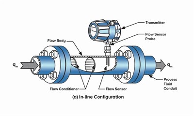
The thermal mass flow meter is available in high-performance Inline type and Insertion type flow meters. Insertion flow meters consist of a probe with sensing elements that are inserted into the pipe irrespective of pipe size. These are easy to install and more economical. Inline flow meters are connected to the pipe itself by the flanged or threaded connection. Inline meters are suitable for smaller diameter pipes.
The thermal mass flow meter is comprised of a family of instruments for precision mass flow measurement. The sensor probe is inserted in the centerline of the flow. Thermal mass flow meters use the concept of heat dissipations for mass flow calculations. Two sensors, both resistive temperature detectors (RTDs), are immersed into the stream of flow under measurement. The first sensor, referred to as a velocity sensor, has a heating element in it and it monitors mass flow rate. The second sensor, which is referred to as a temperature sensor, measures the actual temperature of the gas flowing in the pipe as a reference regardless of the flow velocity. Every gas molecule has the ability to absorb heat. Thus when the gas flows through the pipe, heat from the first sensor (velocity sensor) is absorbed by the gas molecules. As these molecules reach the next sensor (temperature sensor) heat is dissipated and is sensed by this sensor instantaneously. The amount of heat absorbed by the gas molecules is directly proportional to the number of molecules passing the velocity sensor which is nothing but the mass flow rate. This can be mathematically expressed as:
m = K (H/ ΔT)1.67
Where,
m = mass flow rate
K = proportionality constant
H = Heat loss
ΔT = Temperature difference
Two methods, Constant Temperature Difference, and Constant Power are used for mass flow measurement and both methods obtain the same results.
Maintaining a constant temperature difference between the heated (velocity) sensor and a reference (temperature) sensor is the objective of this method. A predefined temperature difference, ΔT, is set during initial calibration. The amount of power to the heater is controlled to maintain the temperature difference. A non-linear relationship between the mass flow rate and power signal is observed. At higher flow velocities, more power is required to maintain the temperature difference. Whereas at low flow velocities, less power is to maintain the temperature difference. This provides excellent low flow sensitivity as well as outstanding turndown.
This technology works on maintaining constant power to the heating sensor. The instantaneous fluid temperature varies depending on the rate of flow and is sensed by the reference temperature sensor. The temperature difference between the heating sensor and reference sensor is constantly monitored. It decreases when the mass flow rate increases. At the lower flow rates, the change in temperature is larger which offers great low flow sensitivity. As the flow rate increases the temperature difference reduces.
Sản Phẩm ENOTEC
Sản Phẩm Của Enotec
Sản Phẩm Của Enotec
Sản Phẩm Của Hãng Sundy
Thiết Bị Đo Áp Suất Yokogawa


0888.755.860